


How CANStepper uses a magnetic encoder to stop missed steps, and two CAN wires to replace twenty.
TL;DR: CANStepper is a small board that bolts onto the back of a NEMA 17 stepper motor. It gives the motor eyes (an encoder that measures where the shaft really is), a voice (a CAN bus, so up to 31 motors share two wires) and a brain (a chip that plans and corrects every move on the motor itself). This post explains each piece from zero.
Who this is for: anyone building a robot arm, camera rig or lab machine where your own program decides what moves. Every term is explained when it first comes up.
Two problems every machine has
Robot arms, 3D printers, camera sliders, lab robots: anything that moves precisely runs into the same two problems.
- Moving exactly where you want. A motor can be told to turn 90° and quietly end up somewhere else, with nobody noticing.
- Talking to many motors at once. Every extra motor usually means another bundle of wires running back to the controller.
CANStepper fixes both. It gives the motor a sensor so it always knows where it really is, and it lets dozens of motors share just two communication wires.
Each idea below builds on the one before it, and short animations show what the words describe.
Meet the stepper motor
A normal motor just spins when you give it power. A stepper motor moves in small, exact jumps called steps, so you can tell it precisely how far to turn.
Inside, a ring of magnets (the rotor) sits in the middle of two sets of wire coils (the stator). When current flows through a coil, it becomes a magnet. Switch the two coils on and off in the right order and the rotor gets pulled from one position to the next, like a dog following a treat you keep moving.
Most steppers take 200 steps for one full turn, so each step is 360 ÷ 200 = 1.8°.
The most common size is NEMA 17: a 42 × 42 mm square face with standard mounting holes. It's the motor inside most 3D printers, and the one CANStepper is built for.

The driver
The chip that decides where a motor should go can only put out tiny signals. The coils need over an amp of current. So a motor driver sits in between: the brain says "next step, this way", and the driver pushes the big current into the coils. CANStepper uses a popular driver chip called the TMC2209.
The driver also does a trick called microstepping. Instead of switching coils fully on or off, it gives them partial currents, so the rotor can stop between the 1.8° positions. At 16 microsteps per step, one turn has 3,200 positions instead of 200. Motion gets much smoother and quieter.
The hidden catch: the driver never knows
The driver sends commands. It never checks whether they happened.
Most of the time that's fine. But if the load is too heavy for a moment (a cable snags, an arm bumps something, the motor accelerates too hard), the rotor can't keep up and skips steps. The driver carries on counting as if nothing went wrong. From then on, every move is off by those missing steps, and the error only grows.
There's a subtler version too. The push available to move the rotor one microstep is tiny: at 16 microsteps it's only about 10 % of the motor's full strength. With a bit of friction, the rotor simply doesn't move for that microstep. Again, the driver never finds out.

That's problem number one: the motor can be told one thing and do another, and nobody knows.
Part 1: Eyes
The fix for problem one is to stop guessing and start measuring.
- Open loop: send commands and assume they happened. Like walking across a room with your eyes shut, counting steps.
- Closed loop: measure what actually happened and correct it. Same walk, eyes open.
To measure the motor, you need a sensor that reads the shaft angle: an encoder. CANStepper uses a magnetic one, the MT6701. A small magnet is fixed to the end of the motor shaft, and the chip sits right underneath it. As the shaft turns, the magnet's field turns with it, and the chip reads the angle.
It's a 14-bit encoder, which means it can tell apart 2¹⁴ = 16,384 positions in one turn. That's about 0.022° each. One 1.8° step is split into about 82 of these tiny marks, so a skipped step is caught within a few thousandths of a second, and even a slip far smaller than a step gets spotted.

The magnet has to be the right kind
The magnet must be diametric: its north and south halves are split across its face, so the field direction turns as the shaft turns. An axial magnet (north on top, south underneath) looks the same at every angle, and the chip can't read anything. Mount it centred over the chip, about 1–2 mm away.

Problem one, solved. Now for problem two: getting all these motors to talk.
Part 2: Voice
Twenty wires: the old way to talk
Chips talk by switching a wire between two voltages: about 0 V means 0, and 3.3 V means 1. Every voltage is measured against a shared reference wire called ground.
The classic way to control a stepper is called STEP/DIR, and it uses separate wires for each motor:
- STEP: every quick pulse means "move one step"
- DIR: sets which way to turn
- ENABLE: switches the driver on or off
- plus wires for limit switches
That's about five wires per motor, all running back to one central controller. Four motors means twenty wires to route and crimp.
The mess isn't the worst part. A STEP wire is just one wire measured against ground. Motors create electrical noise, and if a noise spike on that wire looks like a pulse, the driver counts it as a step. The motor moves when nobody asked it to.

The right side of that animation shows the alternative: every motor sharing one pair of wires. That's CAN.
Two wires: how CAN beats noise
A bus is one shared set of wires that many devices plug into, like a group chat instead of separate phone calls. Every device hears every message, and each message says who it's for.
CAN (Controller Area Network) is a bus invented for cars, where it has to survive engines, sparks and long cables. It uses just two signal wires, CAN H and CAN L, at one million bits per second.
The clever part: CAN doesn't send a bit as "this wire is at some voltage". It uses the difference between the two wires.
- A 1: both wires sit at about 2.5 V. Difference: zero.
- A 0: CAN H goes up to about 3.5 V and CAN L down to about 1.5 V. Difference: about 2 V.
Now suppose noise from a nearby motor cable hits. The two wires run right beside each other, so the noise pushes both of them by the same amount. The difference doesn't change, so the message gets through untouched.

The two wires are also twisted around each other. Each twist flips the little loop between them, so noise picked up by one loop cancels out in the next.

Echoes, and the 120 Ω rule
At a million bits per second, the voltage on the wires changes so fast that each change travels down the cable like a wave.
Picture a rope tied to a wall. Flick one end and a wave runs along it, hits the wall, and bounces back. A cable with nothing at its end does the same: the signal reflects back and crashes into the next bit, scrambling it.
Now tie the rope to something soft that soaks up the wave. No bounce. For a CAN cable, that "something soft" is a 120 Ω resistor. It matches the cable, so the wave is absorbed instead of reflected.

The rule: one 120 Ω resistor, called a terminator, at each of the two ends of the bus, and none in between.
What a message looks like
Every CAN message is called a frame. It carries an ID (11 bits saying what the message is and who it's for) and up to 8 bytes of data.
CANStepper splits the ID into two parts:
- Which board (the node ID): 1 to 31,
- What kind of message: for example, message 4 means "move to this angle"
So "board 1, move to 180°" becomes ID 1 × 64 + 4 = 68, written in hexadecimal (base 16) as 0x44. The angle 180.0 rides along in the 8 data bytes.

One neat property: if two boards start talking at the same moment, CAN sorts it out by itself. The message with the lowest ID always wins, and the other simply waits and tries again. That's why the emergency stop, sent to every board, uses one of the lowest IDs there is. It always gets through first.
Part 3: Brain
The board: a brain on every motor
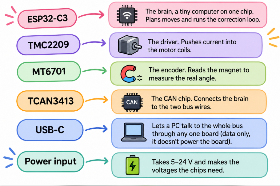
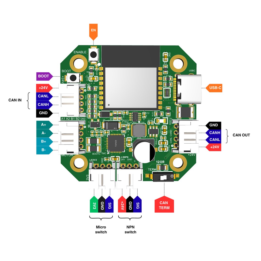
Board pinout from Grafito's CANStepper repository.
The big idea is that the brain lives on the motor. 200 times a second, the board checks where the motor should be, reads where it actually is, and corrects the difference. That loop never leaves the board.
The PC only sends goals, like "board 1, go to 180°". If the PC freezes for a moment, the motor doesn't care. It still knows exactly where it is.
Smooth moves: plan, then follow
Knowing where the motor is isn't enough. It also has to get to the target smoothly, without overshooting.
Step 1: plan the move. Think of driving a car. You don't stamp on the pedal; you press it gently, cruise, then ease off. The board plans every move the same way, as an S-curve: speed builds up smoothly, holds steady, then winds down smoothly. Sudden changes in speed would jolt the machine, like hitting a bell with a hammer. Smooth changes keep it quiet.

Step 2: follow the plan. The usual way to correct a motor is a PID controller. It looks at the error (the gap between where the motor should be and where it is) and pushes to close it. The weakness: it only pushes after the motor has already fallen behind, so it lags and then overshoots.
The fix is feedforward. The plan already says how fast the motor needs to go at every moment, so the board sends that speed straight to the motor, before any error appears. It's like a good driver pressing the pedal before the hill, not after the car slows down. The PID is then only needed to clean up tiny leftovers.

Two motors, one mind
Some machines have a beam carried by a motor at each end, called a gantry: the bridge on a big 3D printer, or a camera crane. If one end moves and the other doesn't, the beam twists and can jam.
You could command both motors from the PC, but if the PC hiccups, one side might get its command a moment late.
CANStepper solves this on the bus itself. Every board already broadcasts its own position, 10 times a second by default (the rate can be raised). So one board becomes the leader, and the other, the follower, is told: "listen to the leader's position and copy it." The PC isn't involved at all.

The follower also checks its own encoder, so it truly matches the leader, and it locks on without a jump when follow mode starts.
Honest limits
Every motor system has edges. Here are CANStepper's, and why they exist.
Why a stepper has a top speed
A motor coil is an inductor: wire wound into a coil, which resists sudden changes in current. Think of a heavy water wheel that takes time to spin up. As the motor turns, the current in its coils has to flip direction again and again. The faster it spins, the less time each flip gets.
At 24 V, the test motor's coil needs about 320 µs for a full flip. At 3000 RPM it only gets 200 µs, so the current only reaches about 65 % of its target. At 5000 RPM it's under 40 %. Less current means less force.
A spinning motor also acts like a small generator, pushing back against its own supply. That's called back-EMF, and it gets stronger with speed, making things worse still.
Why the driver gets hot
Current flowing through anything with resistance makes heat, and that heat grows with the square of the current. Double the current and you get four times the heat. Push hard for long enough and the driver chip warns that it's getting too hot, then shuts itself down to stay safe.

The fix: fit the small heatsink (a finned metal block that spreads heat into the air).
Your first spin
Everything above comes together in five setup steps:
- Start with one board. Connect 24 V power first (USB-C carries data only), then plug in USB and give the board its ID.
- Check the magnet. Diametric, centred over the chip, about 1–2 mm away.
- Calibrate the encoder once, so it corrects its own small errors.
- Add boards one at a time, each with its own ID, and remove the CAN TERM jumper on every board that isn't at an end.
- Power off and measure between CAN H and CAN L. It should read 60 Ω.
Then a few lines of Python move the motor:
from canstepper import CANStepperBus

with CANStepperBus.serial("/dev/ttyACM0") as bus:
    print(bus.discover())               # list every motor on the bus
    node = bus.node(1)                  # talk to board 1
    node.set_run_current(40).enable()   # 40 % current, switch on
    node.move_to(360.0, blocking=True)  # one full turn, wait until done

Where it goes from here
That's the whole journey: a motor that only moves in jumps, given eyes to see where it really is, a voice to talk to every other motor over two wires, and a brain to plan smooth moves on its own. Adding one more axis to a machine is now just one more board on the bus.